This is me again, having no idea about electronics and trying to get a Raspberry Pi to record the temperature of its surroundings in order to better control the environment of the previously mentioned sourdough.
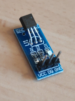
Someone suggested a DS18B20 to me, sorry for forgetting who you are but thanks a lot! It is a "1 Wire Digital Thermometer" and looks like this:

Let's get the absolute basics out of the way: You power it by applying voltage between the
So lets pick three wires and connect some pins (as I said, no idea what I'm doing, so colors are totally random): | Thermometer | Pin on Pi | Pin name | Wire color below | |--- |--- |--- |--- | |
In order to now enable this type of "1 wire" device, add the line

Let's get the absolute basics out of the way: You power it by applying voltage between the
VCC pin and the GND pin and in exchange it will measures the temperature and send it through the DQ pin. The supported range of current necessary to power it can be found under "Supply Voltage" in the datasheet ((https://datasheets.maximintegrated.com/en/ds/DS18B20.pdf)): 3V-5.5V. This is good news because the RaspberryPi happens to have a pin supplying 5V. The datasheet also explains in great detail how exactly the sensor communicates through the DQ pin. But tutorials on the internet suggest that we just need to hook it up to a GPIO pin of the Raspberry Pi.
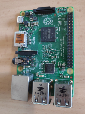
We are now left with identifying the 5V pin, a ground pin and a GPIO pin on the Raspberry Pi. After installing the package python3-gpiozero via apt the command pinout will help with that. Here is an example output on my Raspberry Pi 2 Model B 1.1:
   3V3  (1) (2)  5V
 GPIO2  (3) (4)  5V
 GPIO3  (5) (6)  GND
 GPIO4  (7) (8)  GPIO14
   GND  (9) (10) GPIO15
GPIO17 (11) (12) GPIO18
GPIO27 (13) (14) GND
GPIO22 (15) (16) GPIO23
   3V3 (17) (18) GPIO24
GPIO10 (19) (20) GND
 GPIO9 (21) (22) GPIO25
GPIO11 (23) (24) GPIO8
   GND (25) (26) GPIO7
 GPIO0 (27) (28) GPIO1
 GPIO5 (29) (30) GND
 GPIO6 (31) (32) GPIO12
GPIO13 (33) (34) GND
GPIO19 (35) (36) GPIO16
GPIO26 (37) (38) GPIO20
   GND (39) (40) GPIO21
pinout aligns with the actual pins on the board:

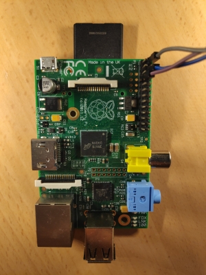
So lets pick three wires and connect some pins (as I said, no idea what I'm doing, so colors are totally random): | Thermometer | Pin on Pi | Pin name | Wire color below | |--- |--- |--- |--- | |
VCC | 2 (top right) | 5V | grey |
| DQ | 7 (forth on the left) | GPIO4 | purple |
| GND | 9 (fifth on the left) | GND | blue |
Which will look like this:

In order to now enable this type of "1 wire" device, add the line
dtoverlay=w1-gpio to /boot/config.txt and reboot the Pi. Then enable the kernel module with modprobe w1-gpio. This will cause the directory /sys/bus/w1 to house files representing all attached 1-wire devices - including the thermometer. Vie the highly sophistication technique called detach-reboot-re-attach-reboot, I determined that the thermometer is represented by a directory starting with 28. This seems to be the same for a lot of people on the internet.
So let's install some Python
apt install python3-venv raspi-gpio python-pip
#!/usr/bin/env python3
# -*- coding: utf-8 -*-
"""
Prints temperature of attached thermometer in milli-celsius on the terminal.
Reference: https://onion.io/2bt-reading-temperature-from-a-1-wire-sensor/
"""
import time
import typing
import re
import glob

import RPi.GPIO as GPIO


class TemperatureSensor:
    RETRY_INTERVAL = 0.5
    RETRY_COUNT = 10

    def __init__(self, channel: int):
        GPIO.setmode(GPIO.BCM)
        GPIO.setup(channel, GPIO.IN)

    def __del__(self):
        GPIO.cleanup()

    @staticmethod
    def read_device() -> typing.List[str]:
        device_file_name = glob.glob('/sys/bus/w1/devices/28*')[0] + '/w1_slave'
        with open(device_file_name, 'r') as fp:
            return [line.strip() for line in fp.readlines()]

    def get_temperature_in_milli_celsius(self) -> int:
        """
        $ cat /sys/bus/w1/devices/28-*/w1_slave
        c1 01 55 05 7f 7e 81 66 c8 : crc=c8 YES
        c1 01 55 05 7f 7e 81 66 c8 t=28062
        """
        for i in range(self.RETRY_COUNT):
            lines = self.read_device()
            if len(lines) >= 2 and lines[0].endswith('YES'):
                match = re.search(r't=(\d{1,6})', lines[1])
                if match:
                    return int(match.group(1), 10)
            time.sleep(self.RETRY_INTERVAL)
        raise Exception(
            F'Cannot read temperature (tried {self.RETRY_COUNT} times with an interval of {self.RETRY_INTERVAL})'
        )


if __name__ == '__main__':
    print(TemperatureSensor(channel=4).get_temperature_in_milli_celsius())
channel parameter accordingly.
Also: pinout for other Raspberry Pi versions may vary radically. Here is the output for a Raspberry Pi Model B 2.0:
   3V3  (1) (2)  5V
 GPIO2  (3) (4)  5V
 GPIO3  (5) (6)  GND
 GPIO4  (7) (8)  GPIO14
   GND  (9) (10) GPIO15
GPIO17 (11) (12) GPIO18
GPIO27 (13) (14) GND
GPIO22 (15) (16) GPIO23
   3V3 (17) (18) GPIO24
GPIO10 (19) (20) GND
 GPIO9 (21) (22) GPIO25
GPIO11 (23) (24) GPIO8
   GND (25) (26) GPIO7
