This blag post describes how to use a [Raspberry Pi](http://amzn.to/2wjICvo) to remotely "press" and potentially "hold" the power button on a PC. This is my first non-trivial (still pretty-trivial) hardware-related project. So don't expect anything too fancy.
## Mainboard
Your PC probably has a power switch and a reset switch. In "modern" ATX power supplies those switches don't directly control the power but merely tell your power supply to toggle power or reset the connection. This is the reason your operating system is able to shutdown properly when you press the power switch on your PC. Please go ahead and try it now... I hope it worked and am happy that you found your way back to this post.
We are now interested in the Pins normally connected to the PC's power switch. They are normally grouped together with the Pins responsible for resetting or that power the case's power LED. To tell an ATX power supply to switch a PC on you have to connect two Pins (and then disconnect them again). This happens when you press (and release) your PC's power button. To find those two Pins, consult the motherboard's manual and find "System panel connector" or similar. In good manuals you will find a schematic displaying the position of the pin group on the motherboard together with a description for every pin. Sometimes pin descriptions are also printed directly onto the mainboard.
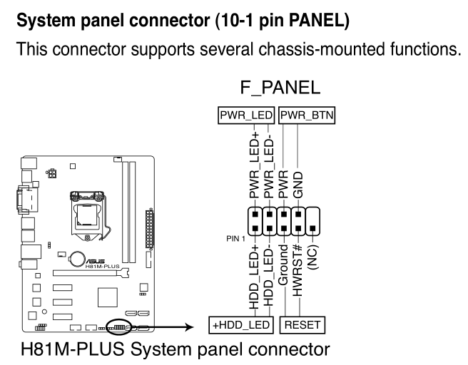
We are interested in the Pin labeled 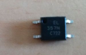
They are numbered from 1 to 4 counter clock-wise starting at the upper left leg (when you orient the thing correctly). If you apply potential to leg 1 and 2, legs 3 and 4 get connected. This is archived through a LED and a transistor: If you apply potential to leg 1 and 2 the LED lights up making the transistor conduct. Hence the name *opto*coupler.

Don't go crazy with the amount of voltage though!
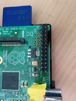
## RaspberryPi
The Pi has a bunch of Pins.
I installed raspbian, GPIO and its Python bindings. GPIO is something you can use to set a potential between a pin and 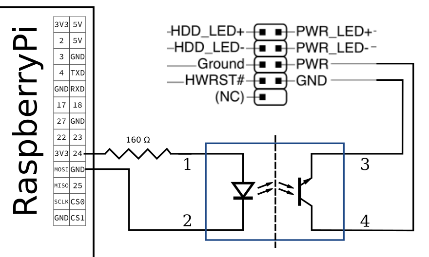
Happy switching.
Edit (2018-10-03): James Foote pointed out a mistake reg. the connected legs of the optocoupler. Thanks and fixed!
PWR and an adjacent Pin labeled GND which stands for *power* and *ground*. Connecting those two is the exact same as pressing (and holding) the power switch.
## Optocouplers
To protect the mainboard from me [screwing up too much](https://blag.nullteilerfrei.de/wp-content/uploads/2017/08/no-idea.png) I decided to isolate the motherboard from all the things I'm doing now. For this a friend recommended so called *optocouplers*. Despite from having a pretty cool name they are like a switch but not usable by humans but by other circuits. For this they have 4 legs:
GND just by calling a command. For this you first have to *mark* a pin as an *output pin* and then set it to *high* (meaning "connect") or *low* (meaning "disconnect"). Then one can do (as root on the pi):
import RPi.GPIO as GPIO
from time import sleep

GPIO.setmode(GPIO.BCM)  # set board layout
GPIO.setup([22, 23, 24], GPIO.OUT, initial=GPIO.LOW)  # mark pins 22 to 24 as output


def press(pin, seconds):
    GPIO.output(pin, GPIO.HIGH)
    sleep(seconds)
    GPIO.output(pin, GPIO.LOW)
press(24, 0.2) then sets pin with number 24 "high" for 200 milliseconds. I set up pin 22 to 24 as output pins because I want to control 3 computers.
## Wiring
If you just connect pin 24 and GND on the Pi with leg 1 and 2 of the optocoupler and then set pin 24 to high most certainly the [magic smoke goes away](https://en.wikipedia.org/wiki/Magic_smoke). So add a resistor to the mix. The rest is straight forward: just connect pin 3 to GND on the motherboard and 4 to PWR:
7 Replies to “Remotely Press a Power Button”