I was always fascinated with the idea of turning ideas into data within a computer and then turning this data into a physical object. With this, I'm probably not alone given that 3D printing is all the rage in nerd world. After some googeling around and buying a printer on Amazon Prime day, I devised the following plan to learn 3D printing as a skill:
1. print sample shape shipped with the printer
2. print model from the internet
3. modify existing model
4. create a model from scratch
The intention behind this plan was to spread out different problems and technologies involves as much as possible. So it's never a daunting task.
# Step 1: Print Sample Shape Shipped with the Printer
First I needed to assemble the printer, a Creality Ender 5 in my case. There seem to be different version of that printer (Pro and non-Pro) and also different firmware version out there (with and without a bed-leveling assistant and with and without runaway protection in case a sensor fails). To avoid bricking my printer as a first order of business, I decided to work with the shipped firmware for now.
The box contains a few larger parts that need assembly, which went very well overall. After finishing, I realized that I should have made sure all pillars are square. So two times the charm, I guess. The wires from the different motors and sensors and the wires that come out of the main control box were all slight different colors. But starting with those that really match and then gradually increasing what counts as, say, "orange" yielded a unique mapping.
Preparing the printer and leveling the bed seems to be an art-form. You can either configure the firmware in a way that it knows the exact height of each part of the bed or you can stick post-it notes under the magnetic mat on the bed to slightly change its height here and there. Since I had this "non bricking"-policy and the configuration involves a firmware update, I went for the second option. Make sure to heat up the bed and nozzle before starting the procedure: things get larger when warm. And as I said in the beginning, preparing the printer seems to be a thing and the sky is the limit: https://teachingtechyt.github.io/calibration.html.
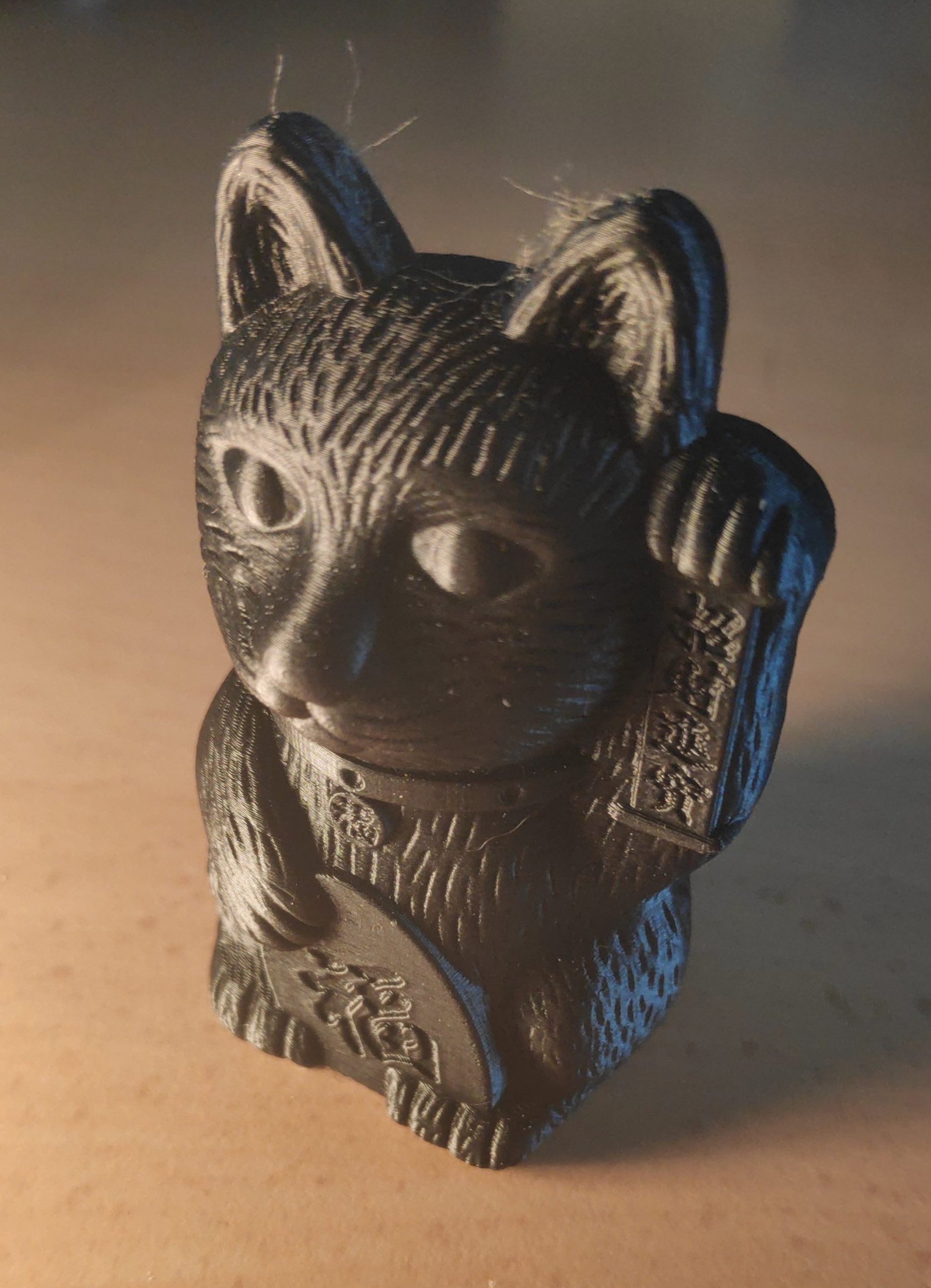
My printer came with an SD card with a few models on it (Dog, Cat and, Pig). So I pushed the filament through the tube and selected one of the models. A few printed layers later, the model stopped sticking to the printing bed and filament went all over the place. This was an easy fix though: I just needed to use the correct bed and nozzle temperatures for the PLA I was using.
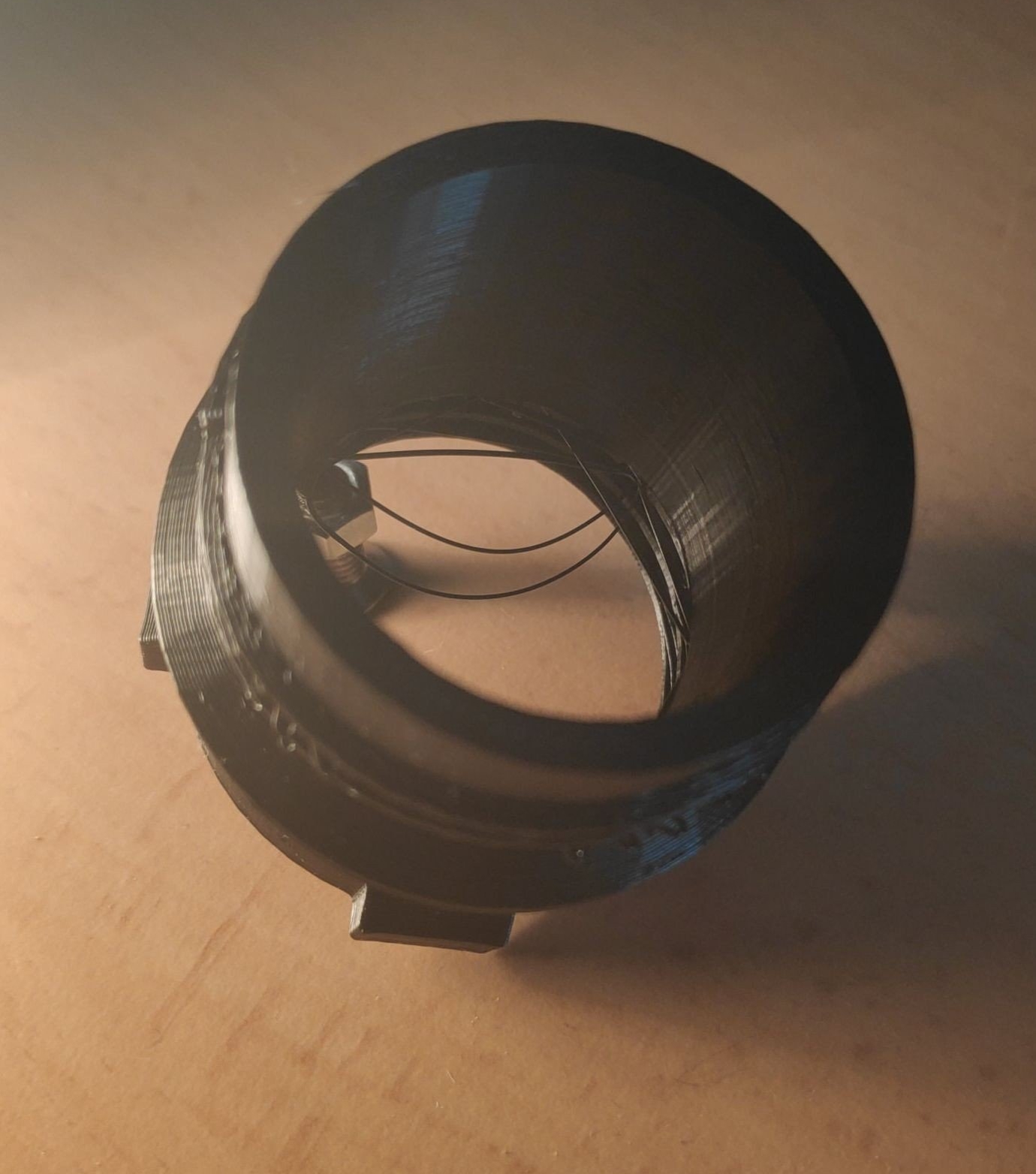
# Step 2: Print Model from the Internet The STL (Standard Triangle Language) file format seems to be the go-to format in the 3D printing world. But an STL file only contains the actual model and no instructions for the printer where to move the nozzle and on what temperature to run and how fast to move and how much filament to push through the nozzle and so on. This is probably because those parameters heavily depend on your exact printer. So one needs to convert a given STL file into a sequence of instructions of an ancient programming language called G-code. This language is generally used to program computer aided manufacturing processes. Hence it's one of those things that are both used by hobbyists like me and by full-time machinists. It seems like an interesting language in the sense that it has a lot of history and one could probably learn a lot about the weirdest manufacturing machines but let's stay on topic here and just get some G-code! A colleague asked me for an adapter for SodaStream bottles between glass bottles and the soda machine for plastic bottles. He said that the machine for plastic bottles is much cheaper. I don't want to talk about questions like "is PLA even food safe" or "the machine for plastic bottle doesn't have a protection against exploding glass bottles". I'm just here for the printing and this sounded like a perfect example for my Step 2 learning experience. There was a software called "Creality Slicer" on the SD card of my printer and previous internet searches suggested that the process of converting models (STL files) to printer instructions (G-Code) is called slicing. The Creality Slicer just seems to be a branded version of the Cura software, but I just went with it for the time being. The STL file from Thingiverse came with the following instructions: "No supports required. Print with 100% infill and use o-ring or similar seal when screwing adapter onto glass bottle. 0.15 mm layer height works great. Both PLA and PET work. PLA is my personal preference.". The important bits are * no supports * 100% infill * 0.15mm layer height So I set the corresponding values in the slicer software, left everything else on defaults, exported the resulting G-code to the SD card, and started printing. I'd like to say a word about the "platform adhesion type": this is the technique, the slicer uses to make the model stick to the printing bed so it doesn't move around. Mine had "Raft" pre-selected and that seems to be that thing under every print that you can easily rip off after printing. The results had some overhang in the screw thread for the buttle but I am not sure it is even possible to avoid something like that in a low-budget printer like mine. So I just decided that this is a "post processing" thing: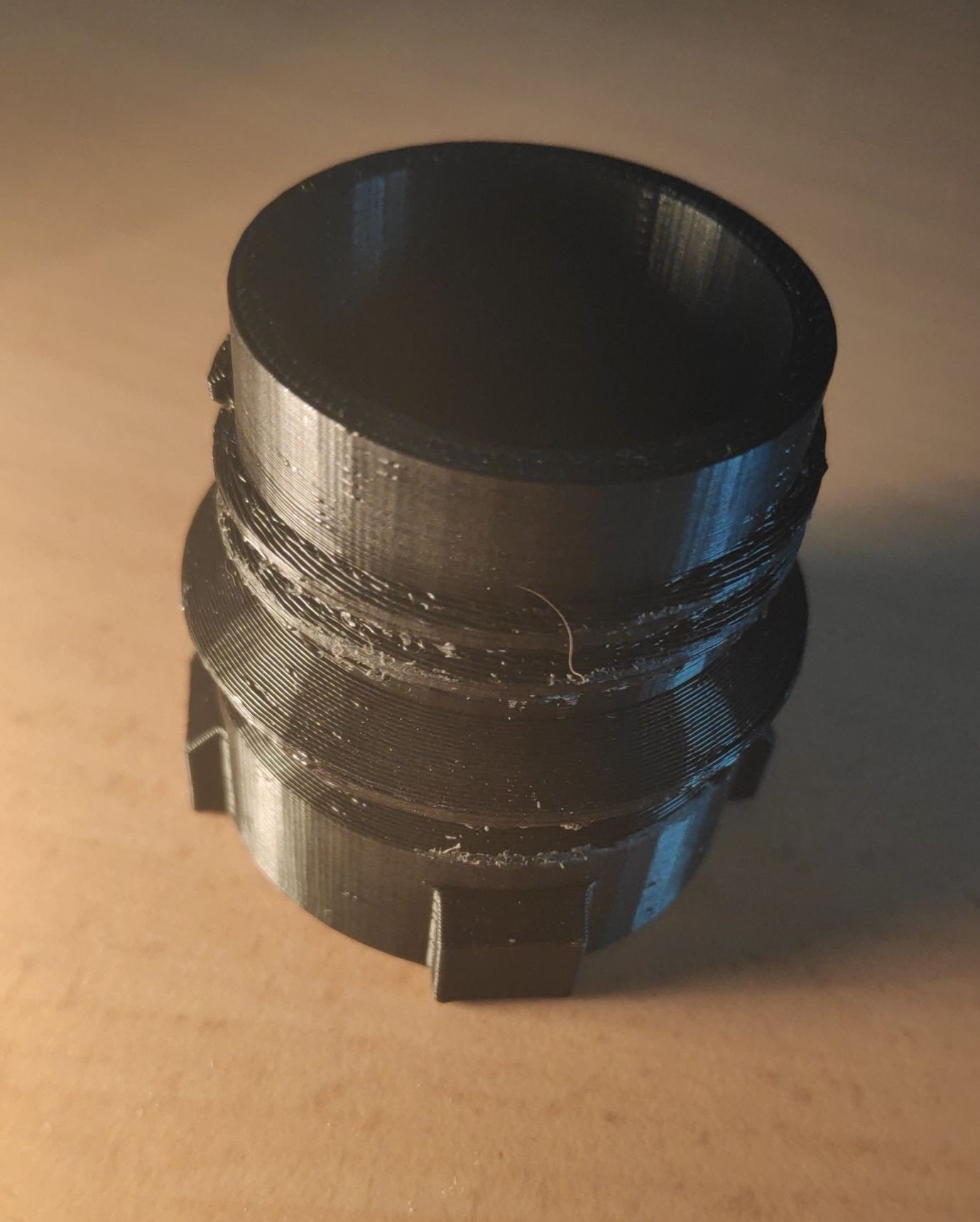
# Step 3: Modify Existing Model Step 3 should involve editing of an existing 3D model so I not only touch a "slicer software" but also a real CAD or modeling software. The same colleague as above had another request: a camera grip. He bought the model online and it looks like this in the slicer: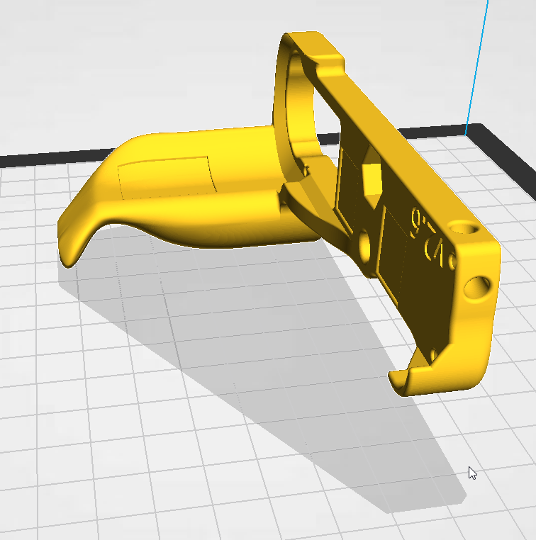
It also came with instructions: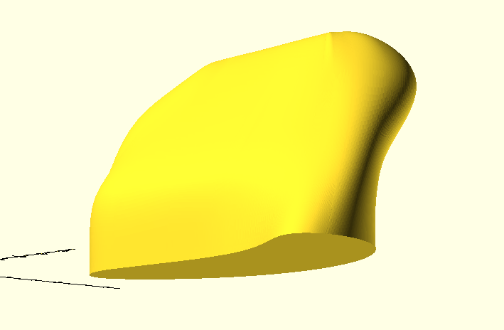
But I wasn't able to slice this model. Probably because it's just the "shell" of the upper part and not "solid". So I went back to MeshLab and used the following feature: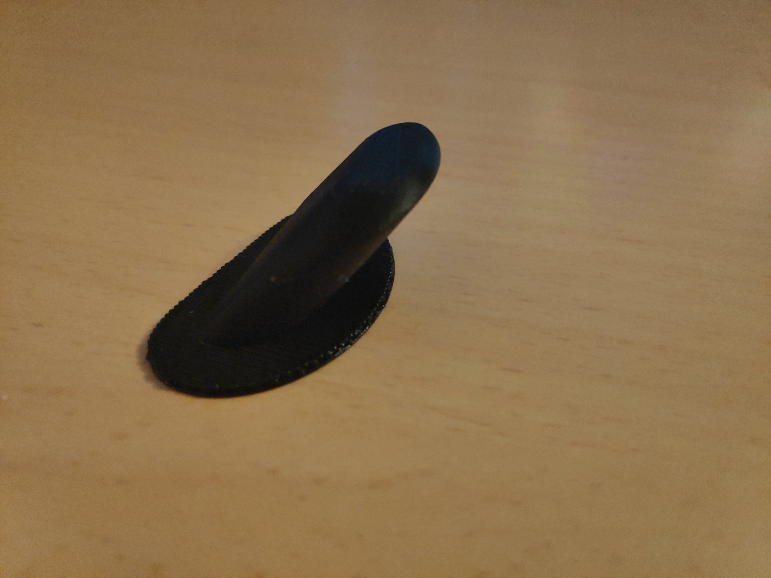
To summarize: * download STL * repair it and add a convex hull with MeshLab * rotate and cut out upper part with OpenSCAD * use same slicer as in Step 2 to generate G-Code * print G-Code As you might have noticed on the above print: the part printed fine even with a 45° overhang. So all that's left was to draw the rest of the fucking owl: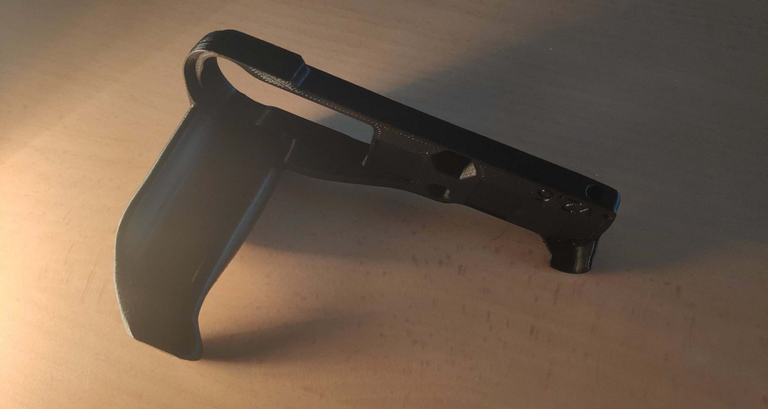
# Step 4: Create a Model from Scratch I have this following extendable arm mounted next to my desk: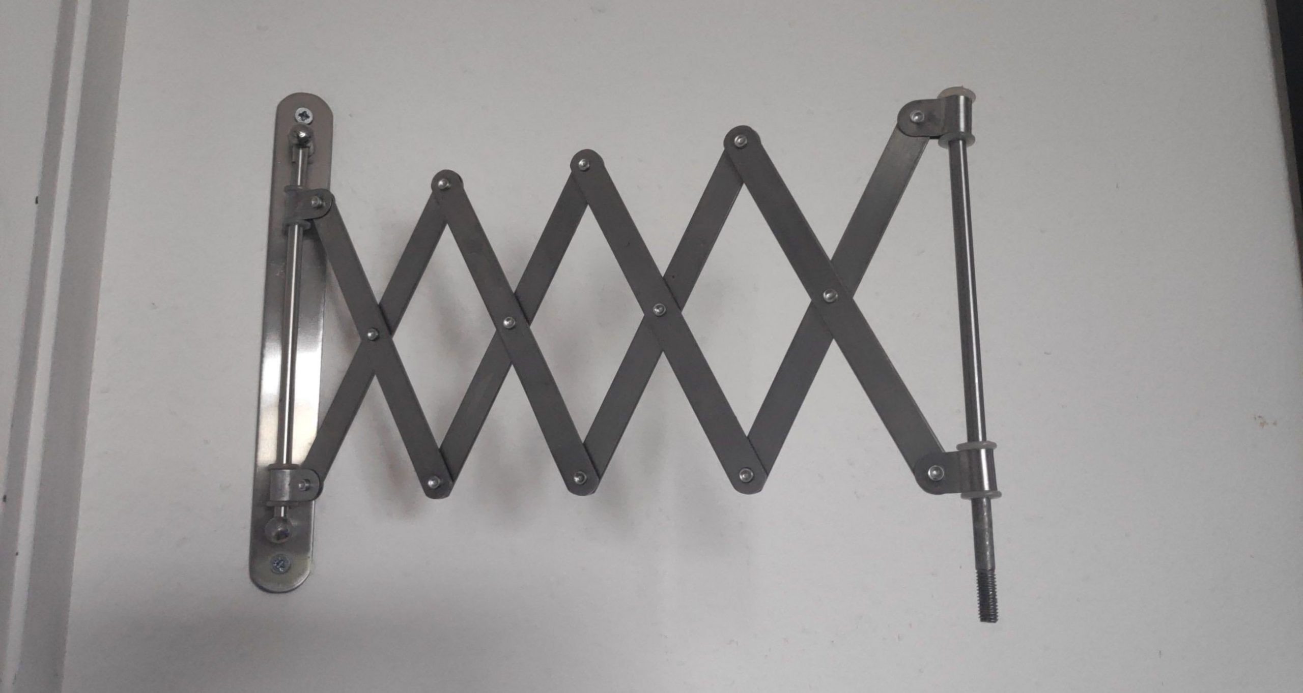
And I also have the following lamp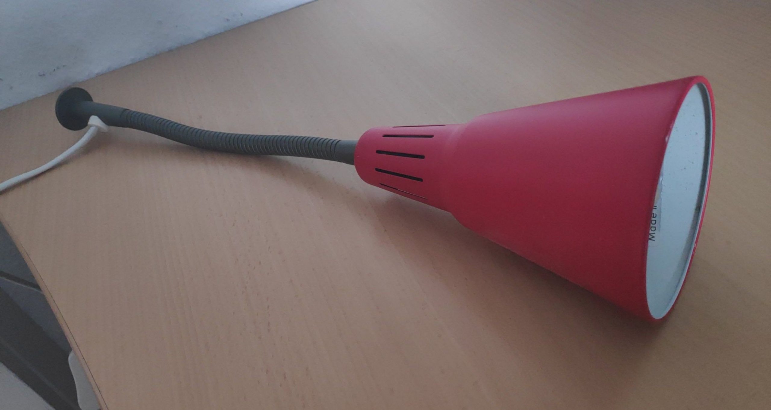
As a first "from scratch" project, I decided to create a "mount" to connect the two somehow. The plan is to let the lamp "stick out" at 90 degree. After measuring all threads involved, I found the following metal parts in my basement.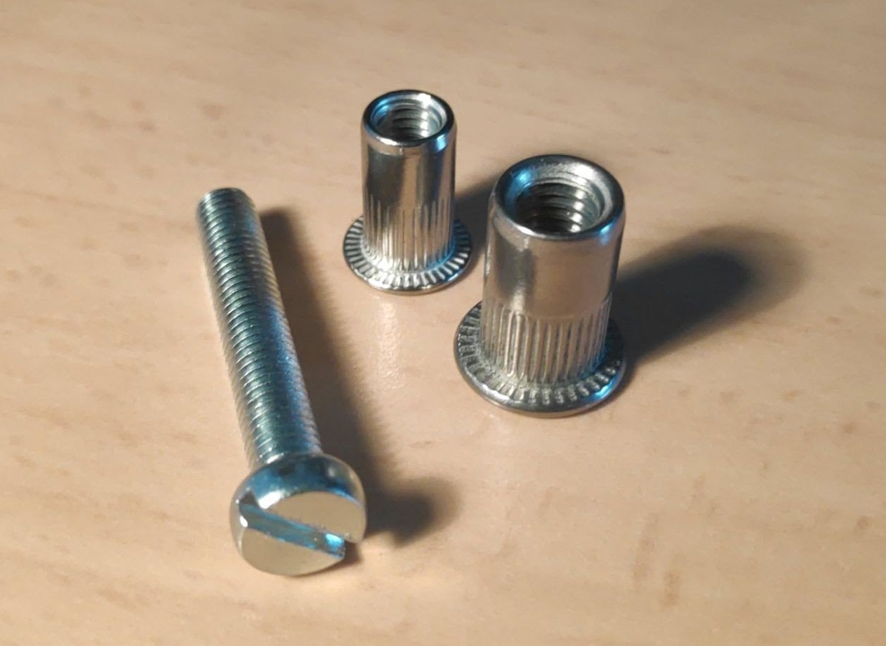
Also pay close attention to the base of the lamp: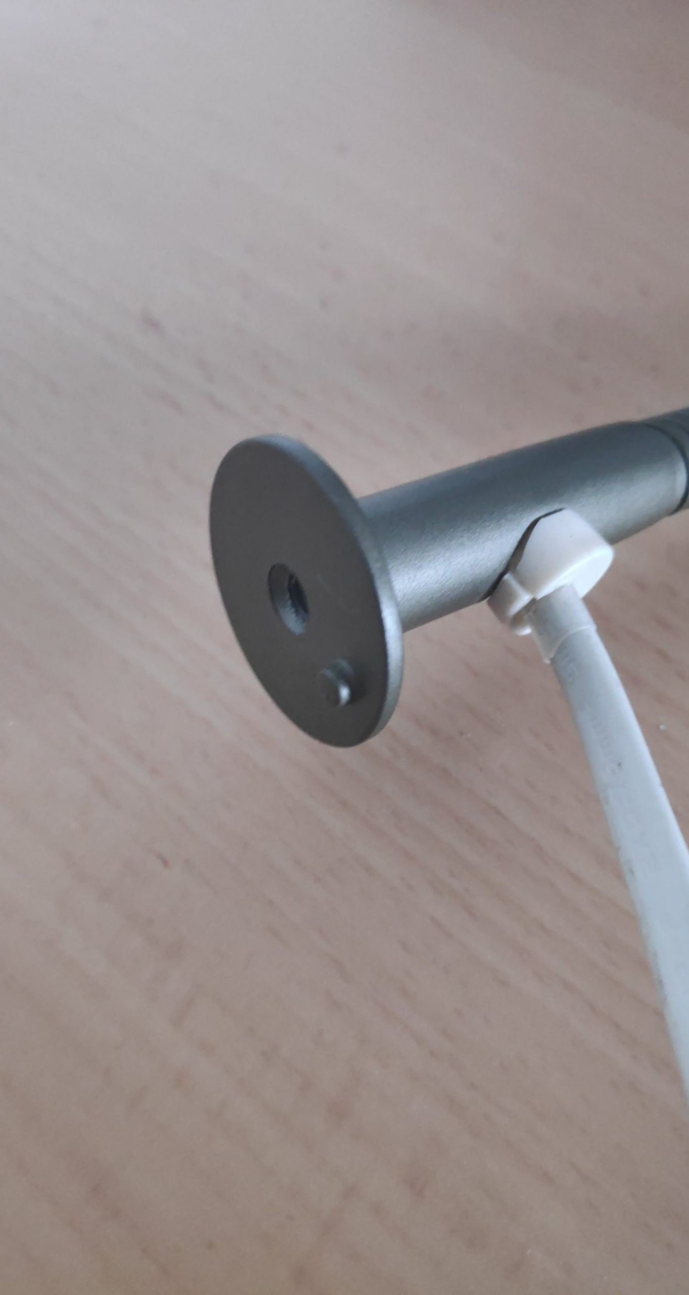
The philosophy behind software like OpenSCAD seems to be to construct complex forms by combining simple geometric forms. The software supports different operations like "union" and "difference". We will only be using the later. So starting with a scaled cube of dimensions 20 x 60 x 40, we consecutively carve out the holes for screws and threads: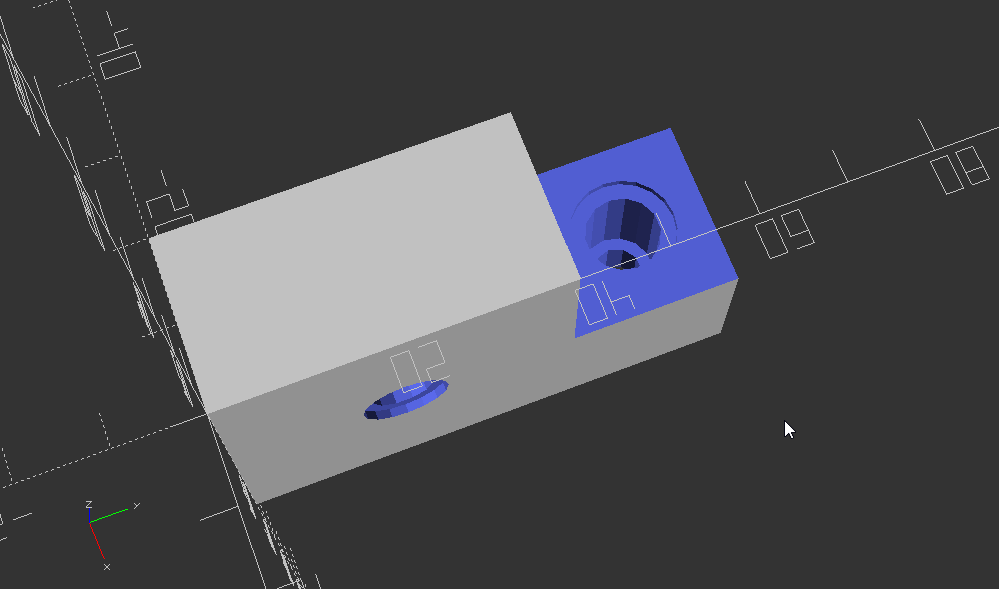
Printing it took roughly 2 hours with 30% infill: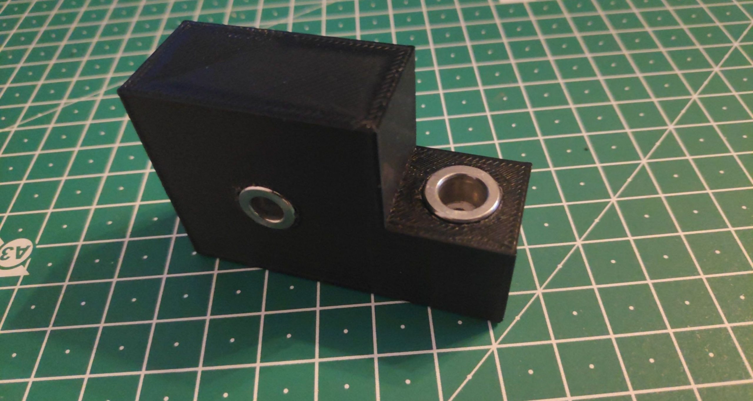
And here the fully assembled result: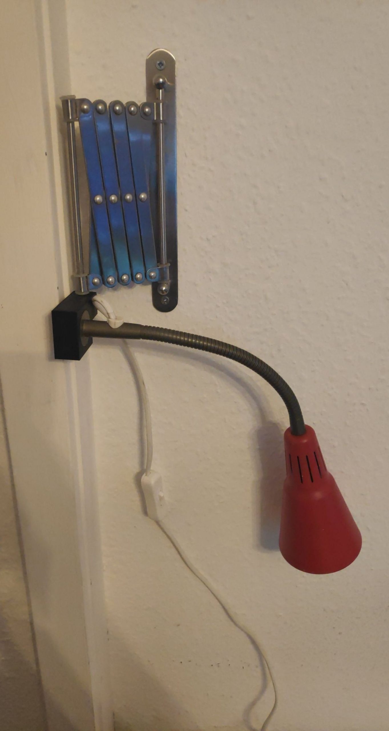
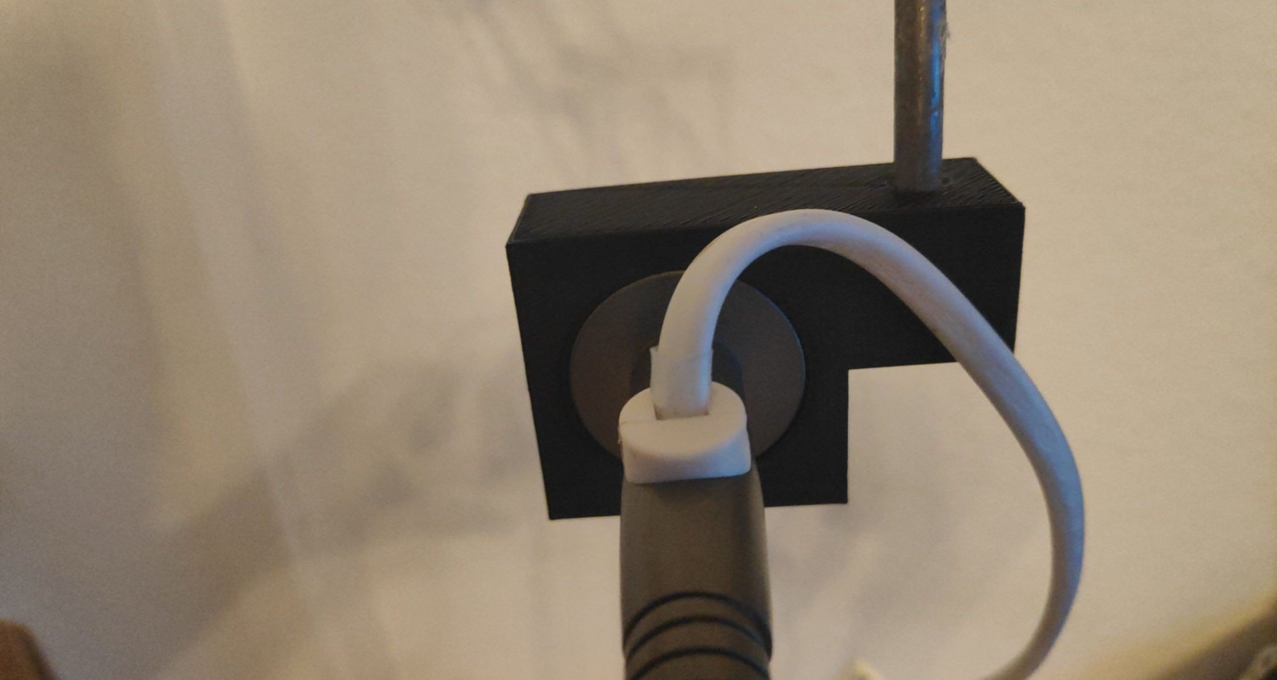
One thing I'd like to send back my past-self from 2 hours ago: make everything a tiny bid wider then you measured, otherwise you'll have to do a bit of sanding in the post-processing step.

# Step 2: Print Model from the Internet The STL (Standard Triangle Language) file format seems to be the go-to format in the 3D printing world. But an STL file only contains the actual model and no instructions for the printer where to move the nozzle and on what temperature to run and how fast to move and how much filament to push through the nozzle and so on. This is probably because those parameters heavily depend on your exact printer. So one needs to convert a given STL file into a sequence of instructions of an ancient programming language called G-code. This language is generally used to program computer aided manufacturing processes. Hence it's one of those things that are both used by hobbyists like me and by full-time machinists. It seems like an interesting language in the sense that it has a lot of history and one could probably learn a lot about the weirdest manufacturing machines but let's stay on topic here and just get some G-code! A colleague asked me for an adapter for SodaStream bottles between glass bottles and the soda machine for plastic bottles. He said that the machine for plastic bottles is much cheaper. I don't want to talk about questions like "is PLA even food safe" or "the machine for plastic bottle doesn't have a protection against exploding glass bottles". I'm just here for the printing and this sounded like a perfect example for my Step 2 learning experience. There was a software called "Creality Slicer" on the SD card of my printer and previous internet searches suggested that the process of converting models (STL files) to printer instructions (G-Code) is called slicing. The Creality Slicer just seems to be a branded version of the Cura software, but I just went with it for the time being. The STL file from Thingiverse came with the following instructions: "No supports required. Print with 100% infill and use o-ring or similar seal when screwing adapter onto glass bottle. 0.15 mm layer height works great. Both PLA and PET work. PLA is my personal preference.". The important bits are * no supports * 100% infill * 0.15mm layer height So I set the corresponding values in the slicer software, left everything else on defaults, exported the resulting G-code to the SD card, and started printing. I'd like to say a word about the "platform adhesion type": this is the technique, the slicer uses to make the model stick to the printing bed so it doesn't move around. Mine had "Raft" pre-selected and that seems to be that thing under every print that you can easily rip off after printing. The results had some overhang in the screw thread for the buttle but I am not sure it is even possible to avoid something like that in a low-budget printer like mine. So I just decided that this is a "post processing" thing:


# Step 3: Modify Existing Model Step 3 should involve editing of an existing 3D model so I not only touch a "slicer software" but also a real CAD or modeling software. The same colleague as above had another request: a camera grip. He bought the model online and it looks like this in the slicer:

It also came with instructions:
Print settings:
- Make sure the grip stands upright for printing. This is the recommended orientation.
- Layer height of 0.1mm provides very good results. You can use thicker layers for faster prints or for prototyping.
- Supports are needed for the tripod screw hole.
- The upper grip part contains an overhang of more than 45 degrees.
  It is recommended that you do a small test print of the upper grip part to ensure your printer can handle it without support.
- Infill: 30% is recommended. Several internal ribs have been added to ensure stability even without very high infill.
  You might be able to lower the infill further and still achieve very good stability.
- Perimeter: 3 @ 0.4mm nozzle (1.2mm total). This should provide sufficient stability in thin parts.
- For improved printing quality, it is strongly recommended to add a thin support cylinder under the main tripod hole.
  This will dramatically improve the quality of the printed hole, and the surrounding fillets.
translate([0,-30,-50])
    intersection() {
        rotate([90,0,0])
            import("grip_v2.6.stl");
        translate([-10,30,50])
            cube(50);
    }
ERROR: CGAL error in CGAL_Nef_polyhedron3(): CGAL ERROR: assertion violation! Expr: e_below != SHalfedge_handle() File: /mxe/usr/x86_64-w64-mingw32.static.posix/include/CGAL/Nef_3/SNC_FM_decorator.h Line: 426
Filters -> Cleaning and Repairing -> Remove T-Vertices by Edge-Flip and put in 1000000 as the ratio:
Successfully removed 7 t-vertices
Applied filter Remove T-Vertices by Edge Flip in 267 msec
grip_v2.6.stl in OpenSCAD then yielded only the "upper part":

But I wasn't able to slice this model. Probably because it's just the "shell" of the upper part and not "solid". So I went back to MeshLab and used the following feature:
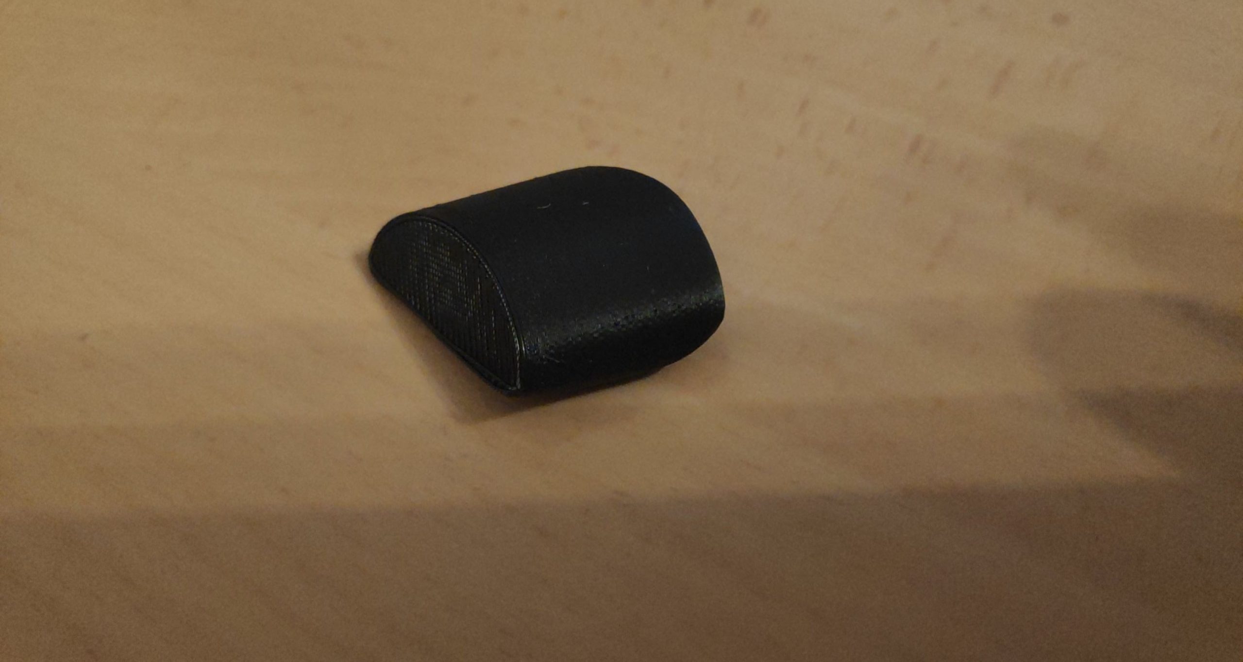
Filters -> Remeshing, Simplifaction & Reconstruction -> Convex Hull. This left me with a model that I could slice and finally print:


To summarize: * download STL * repair it and add a convex hull with MeshLab * rotate and cut out upper part with OpenSCAD * use same slicer as in Step 2 to generate G-Code * print G-Code As you might have noticed on the above print: the part printed fine even with a 45° overhang. So all that's left was to draw the rest of the fucking owl:

# Step 4: Create a Model from Scratch I have this following extendable arm mounted next to my desk:

And I also have the following lamp

As a first "from scratch" project, I decided to create a "mount" to connect the two somehow. The plan is to let the lamp "stick out" at 90 degree. After measuring all threads involved, I found the following metal parts in my basement.

Also pay close attention to the base of the lamp:

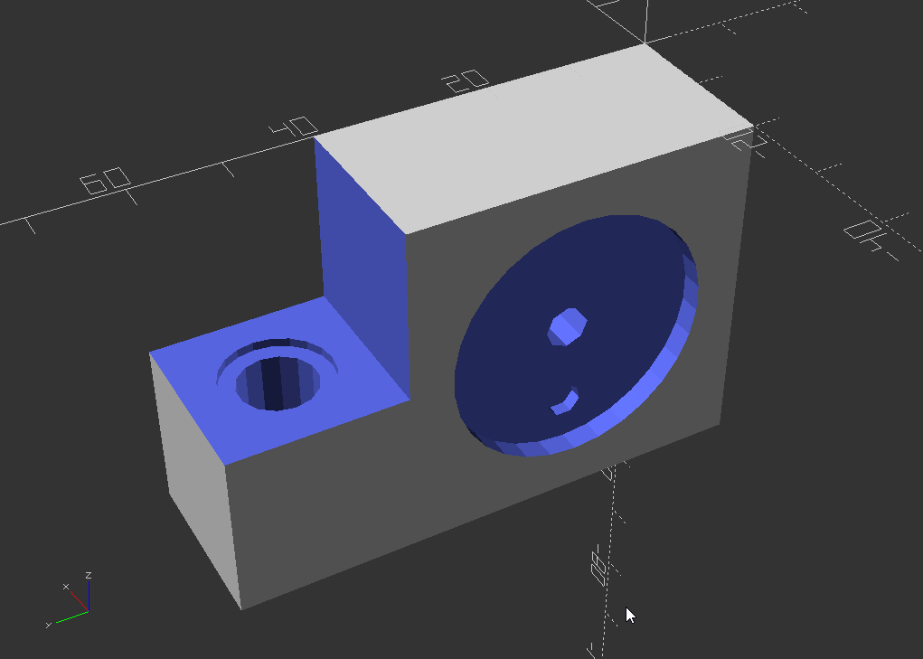
The philosophy behind software like OpenSCAD seems to be to construct complex forms by combining simple geometric forms. The software supports different operations like "union" and "difference". We will only be using the later. So starting with a scaled cube of dimensions 20 x 60 x 40, we consecutively carve out the holes for screws and threads:
rotate([0,180,0])
difference() {
    scale([20, 60, 40]) cube(1);

    // cut out
    translate([-1,40,-1]) scale([22, 21, 21]) cube(1);

    // hole for lamp
    translate([-1,20,20]) rotate([0,90,0]) cylinder(40, 2.5, 2.5);
    // slot for lamp
    translate([20-2.5,20,20]) rotate([0,90,0]) cylinder(5, 15, 15);
    // slot for "nipple" on lamp
    translate([16,20,35-3-2]) rotate([0,90,0]) cylinder(3,2,2);
    // screw thread head for lamp
    translate([-1,20,20]) rotate([0,90,0]) cylinder(2, 5, 5);
    // screw thread for lamp
    translate([-1,20,20]) rotate([0,90,0]) cylinder(14, 3.5, 3.5);

    // hole for wall mount
    translate([10,50,-1]) rotate([0,0,0]) cylinder(42, 3, 3);
    // thread for arm mount
    translate([10,50,20-1]) rotate([0,0,0]) cylinder(15, 8.8/2, 8.8/2);
    // head of thread for arm mount
    translate([10,50,20-1]) rotate([0,0,0]) cylinder(2, 12.4/2, 12.4/2);
}


Printing it took roughly 2 hours with 30% infill:


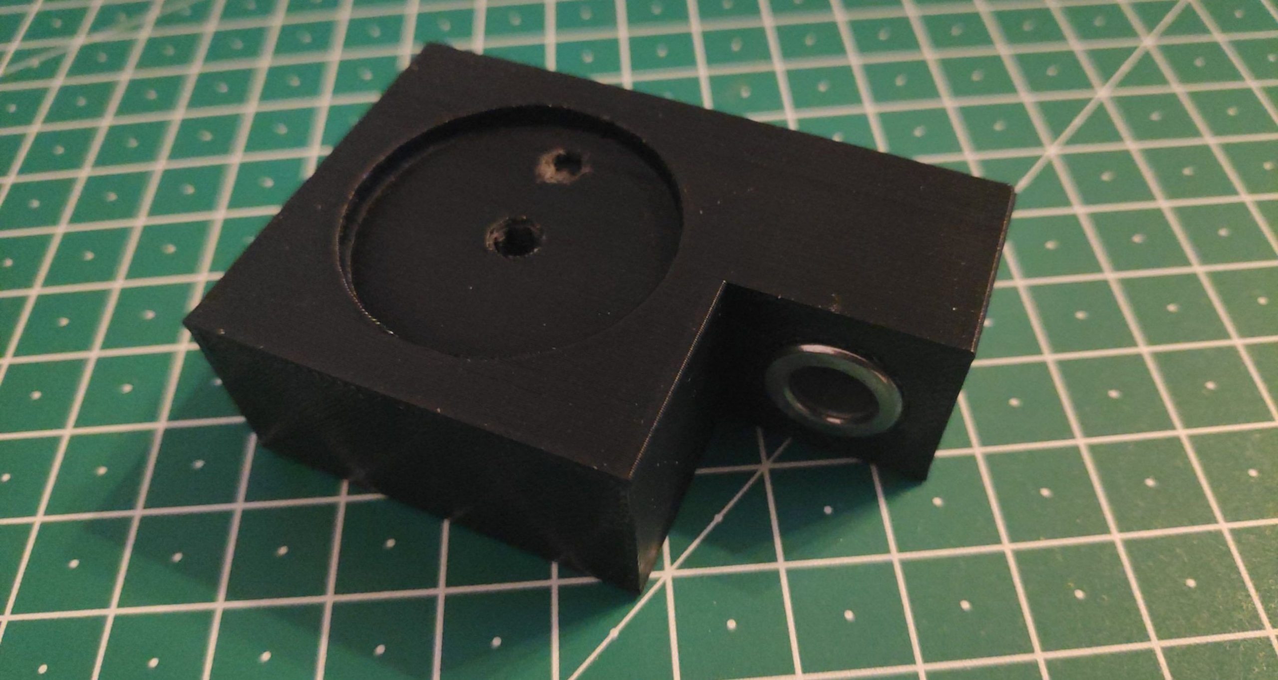
And here the fully assembled result:


One thing I'd like to send back my past-self from 2 hours ago: make everything a tiny bid wider then you measured, otherwise you'll have to do a bit of sanding in the post-processing step.